FLORIDA LATE MODELS RULES PACKAGE
Chassis/Frame
A.) The minimum wheel base will be 103”.
B.) All frames must be fabricated from magnetic steel with a minimum of 2” x 2” or approved rectangular magnetic steel with a minimum material thickness of .083”.
C.) A minimum of 1.75” Outside Diameter magnetic steel tubing, 4130 Chrome Moly or DOM with a minimum material thickness of .083”, will be permitted for frames that are fabricated from round tubing.
D.) Rear bumpers that are stubbed may only extend a maximum of 8” beyond the frame. Any stubbed rear bumper that extends further than the maximum of 8” must be formed and directed 8” toward the front of the car.
E.) External rub rails will not be permitted.
F.) All cars must be equipped with a tow hook and/or strap for the purpose of towing.
G.) All battery supports and/or mounts must be secure and braced in two (2) horizontal positions and one (1) vertical position.
Weight / Ballast
A.) Weights up to 50 lbs must be positively fastened by (2) 1/2″, minimum grade 5 bolts, with a minimum of two weight clamps. Threaded rods will not be permitted. All weights must be painted white and clearly labeled with the car number on it.
B.) Any weight(s) must be securely attached to the frame below the body decking. C.) Any car that loses any weight/ballast during an event will be subject to a penalty.
D.) Weights attached to the rear bumper and/or outside the frame will not be permitted. E.) Pellet-type and/or liquid-type weight/ballast will not be permitted. Tungsten will not be permitted.
F.) Driver operated weight adjustment, ‘weight jacking’ devices will not be permitted.
G.) The scales used for the event, provided by the track, will be considered the official scales for the event.
H.) Scales will be available for any team to verify its car weight and determine the scale weight. I.) Officials will allow a car to re-scale two times by pulling off scale and pulling back on.
Reading of the third attempt will become the entered weight.
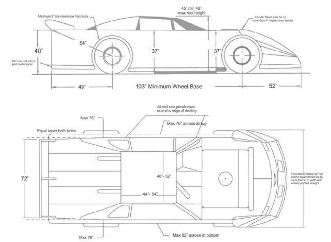
Body (Refer to diagrams attached) Overall Appearance
A.) The car must be neat in appearance and must display the car number of the front nose and the
rear fuel cell. The minimum height for the number will be 6” inches.
B.) The car must have legible numbers on each side and on the roof a minimum of 18” inches high.
General Body
A.) The nosepiece must match the body style of the make and manufacturer of the car and be the same as the make and manufacturer of the motor (GM, Ford, Mopar).
B.) All cars must have a minimum half-inch (1/2”) and a maximum of one inch (1”) radius at the top of fenders, doors and quarter panels. Sharp edge(s) will not be permitted.
C.) The floorboards and firewall must completely cover the driver’s area with no openings.
D.) Fins and/or lips of any-type will not be permitted anywhere along the entire length of the car. E.) The bodyline must be a smooth even line from front to rear.
F.) Wedge shape cars and/or body styles will not be permitted.
G.) “Belly pans” or any type of enclosure on the bottom of the car will not be permitted. A skid plate to protect the oil pan is permitted.
H.) Wings and/or tunnels and/or any type of air deflection device will not be permitted underneath the body and/or chassis of the car.
I.) Panels of any type under the rear deck running from the front to the rear of the car will not be permitted.
J.) Any style air cleaner scoop used must be positioned in front of/or around the air cleaner and must not exceed 1” in height above any part of the air cleaner. Any type of flange and/or air deflection device and/or fin that is designed to direct airflow will not be permitted.
K.) Cockpit adjustable components with the exception of brake bias adjusters will not be permitted. Adjusters of any-type, including but not limited to adjustable shocks, hydraulic or pneumatic weight jacks, trackers, ignition boxes or similar adjustable components will not be permitted inside the cockpit of the car or within reach of the seated driver.
L.) The top edge, measured from the ground, of the rear quarter, door and front fender to the point where the fender flare attaches must be a straight line, within 1” on both sides of the car.
Nosepiece
A.) Only approved nose pieces will be permitted.
- Dominator
- Five Star – Performance Bodies
- ARP
B.) Approved nose assemblies must be installed per the manufactures instructions. All nose assemblies must meet the maximum/minimum dimensions, shall maintain manufacture appearance and not be altered.
C.) All nosepieces must be made of molded type material.
D.) Nose filler panel shall be flat across entire surface, dishing or raising prohibited.
E.) Two piece noses must be positively fastened together in the center. Spacers added to gain width will not be permitted.
F.) The nosepiece must be mounted in a manner that does not alter its original shape.
G.) The nose shall remain flat above the nose lip/wicker bill. Alterations and/or additions may be made to this area other than cooling holes will not be permitted.
H.) The nosepiece can extend a maximum of fifty-two inches (52”) from the center of the front hub to the farthest point extending forward.
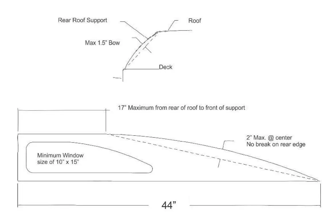
Roof
A.) Roof length from front-to-back must be a minimum of 44” and a maximum of 54”. B.) Roof width from side-to-side must be a minimum of 48” and a maximum of 52”.
C.) The roof must be stock appearing and be mounted level to the body.
D.) The minimum height of the roof will be 45” with a maximum height of 48”.
E.) The roof must be mounted parallel to the body and near the center of the car as viewed from the front of the car.
F.) A maximum 1-1/2” roll, turned downward will be permitted along the front of edge of the roof. A maximum1” roll, turned downward, will be permitted along the rear edge of the roof. These modifications will be permitted to improve the strength of the roof. Any other modifications to the roof will not be permitted.
G.) Flat and/or odd shaped roofs, bellied and/or hollowed roofs will not be permitted.
H.) Any sun/antiglare shields may not exceed a 4” drop from the top roof line, and must hinge for easy exiting.
I.) A maximum of two (2) roof edge bead rolls of a maximum height of ½”- inch the length of the roof will be permitted.
J.) The roof posts and spoiler support(s) may not overlap. K.) Only single plated roofs will be permitted.
L.) The maximum thickness of the roof at any point will be 1/2”.
M.) The roll cage and associated frame members above the interior panels (decking) must remain open. Enclosures will not be permitted.
Roof Supports and Window Side Panels
A.) All roof side panels must extend to the edge of the body.
B.) The roof side panel window size must be a minimum of 10” x 15” and must match drawing number -2- side view. A maximum crown of 2” will be permitted, measured from the center of a common tangent point on either side of the crown.
C.) The side window area may be covered with clear Lexan and/or equivalent type material, be cut out and/or represented by a decal. Both roof support openings must be covered and/or both must be left open. The left and right side openings must be the same size with a tolerance of 1”. D.) The left and right side window panels must match.
E.) A maximum bow of 2” outward on the window side panels as viewed from behind will be permitted.
F.) The front roof supports up to 2” in width must extend forward to the rear of the hood.
Front Fenders, Fender Flares and Hood
A.) The hood and the front fenders must be level and flat from the left to the right side of the car. B.) The outside edges of the hood and/or the fender must remain inside the overall bodyline.
C.) The front fender may be a maximum of 37” in height, measured vertically from the ground to the top of the fender behind the front tires.
D.) The front fender flares must be made of plastic and must not alter the original shape of the nose piece.
E.) The front fender flares must not extend beyond the front tires more than 1” per side to a maximum width, edge-to-edge, of 90” in width with the wheels pointed straight.
F.) The front fender flares must be flat across the entire width of the car. Front fender flairs shall not extend, bubble or rise more than a maximum of 4” at any point of the front fenders and/or hood.
G.) The front fender flares must have collapsible supports.
Doors
A.) The door-to-door measurement must not exceed 76” in width at the top of the doors.
B.) The door-to-door measurement must not exceed 82” in width when measured at the bottom of the doors in the center of the car. The doors must not exceed 37” in height when measured from the ground to the top of the door. The measurement from the ground to the top of the door, on both sides of the car, right door and left door, must measure within a 1” variance.
C.) The door sides may not break inward from the top 76” and bottom 82” measurements. Hollow and/or bellied doors will not be permitted.
D.) The minimum ground clearance will be 3”.
Quarter Panels
A.) The maximum distance from the center of the rear hub to the top quarter of the panel is 54”. B.) The quarter panels must not exceed 76” in width at any point as measured at the top of the panels.
C.) The rear deck must taper in a symmetrical manner from the center of the rear hub to the rear spoiler with a minimum width of 72” and a maximum width of 76”.
D.) The maximum width for the quarter panels measured from outside to outside measured 19” from the ground and/or at the bottom of the quarter panel will be 86”.
E.) Any breaks and/or bends formed in the sides of the quarter panel that move the panel toward the center of the car will not be permitted. Hollow and/or bellied panels will not be permitted.
F.) The maximum distance from the center of the rear hub to the rear trailing edge of the quarter panel will be 49”.
G.) G,) The maximum height from the ground to the top of the rear deck at the top of the rear quarter panel is 40” checked pre-race.
H.) A minimum of 2” of tire clearance between the tire and the body will be required. I.) Skirting that extends behind the rear quarter panel will not be permitted.
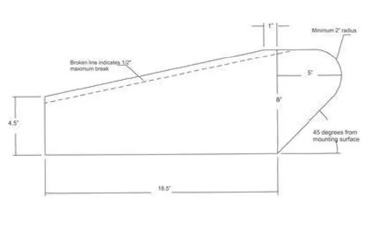
Spoilers and Spoiler Braces/Supports
A.) Only aluminum and/or Lexan and/or Lexan-type rear spoilers will be permitted.
B.) The maximum overall height of the rear spoiler will be 8”. The maximum width of the rear spoiler, including braces and/or supports is 72”.
C.) The rear spoiler must begin at the deck and extend 8”-inches from that point. Suspending the spoiler to create a wing-type device will not be permitted.
D.) The rear spoiler must begin at the rear most point of the quarter panels.
E.) Only three spoiler braces/supports will be permitted. The front edge of the spoiler brace/support must be in line with the spoiler.
F.) The outside spoiler supports must not be mounted any wider than the top of the quarter panel(s) and must be centered on the rear deck.
G.) In the event that aluminum angle is used to bracer the upper edge of the spoiler, the angle must not add to the height and/or length of the spoiler in any way.
Interior
A.) The interior of the cockpit must be a minimum of 11” below the top of the roof and/or roll cage, measured perpendicular to the ground from the bottom of the roof to the cockpit deck. Roof rolls are not part of the measurement.
B.) The side window opening(s) must be 15” from the top of the door to the bottom of the roof. C.) Supports bars that block the right window from the driver exiting will not be permitted.
D.) A single rock guard (Lexan screen) tapered back from the steering wheel to the height of 1” in line with the driver’s chest providing the 11” minimum clearance is met at any point from the roll cage to the body and/or rock guard.
E.) If the interior deck drops the drop must begin at the rear of the engine plate with a maximum of 4” and must not drop below 4” rear of the hood. The start of the dropped interior must remain closed as a part of the fire wall. The entire width must be closed off with sheet metal.
F.) The interior must gradually taper up to the quarter panel height and must be level for a minimum of 20” from the rear of the quarter panel and deck.
Driver Compartment
A.) A full metal firewall fabricated from magnetic steel and/or aluminum must encompass the driver’s compartment from front-to-rear, on both sides and floor boards.
B.) The driver’s seat must be a high back aluminum seat, designed for racing, located on the left side of the car and mounted per the manufacturer’s instructions securely to the frame.
C.) The seat design should be one from a current manufacturer and/or recommended to include the full containment design. Installation should follow the manufacturer’s instructions.
D.) All cars must be equipped with a quick-release type steering wheel.
E.) The driver compartment must have a starting switch and/or button within reach of the driver. F.) A clearly labeled electrical on/off ‘kill’ switch within reach of the driver is recommended.
G.) Mirrors of any-type will not be permitted.
H.) Radios, electronic or data communication devices other than Raceceiver are not permitted. I.) Any edge and/or sheet metal end in and around the driver compartment must be protected with trim and/or beading and rounded. Sharp and protruding edges will not be permitted.
J.) A substantial rock guard with a minimum of three (3) additional roll bars must be mounted in front of the driver.
Weight
A.) Cars utilizing a GM 602 crate engine (with any Carb.) or a Ford 347JR crate engine (with Holley 4412 2-barrel) shall weigh a minimum of 2200 lbs. post-race minus 1 lb. per lap burn off. B.) Cars utilizing a GM 604 crate engine or a Ford 347SR crate engine shall weigh a minimum of 2450 lbs. post-race minus 1 lb. per lap burn off.
C.) Cars utilizing a rules specified built engine shall weigh a minimum of 2500 lbs. post-race minus 1 lb. per lap burn off.
D.) Any car having an engine setback of more than 6” inches measured from #1 spark plug to center of ball joint on the left front upper control arm shall add 25 lbs. of penalty weight for every 1/2“ past 6”.
E.) Weight reduction bonuses to be taken off the minimum post-race weight are as follows
- 25 for the use of an approved head and neck restraint.
- 25 for the use of an approved full containment seat.
- 25 for the use of an approved non driver activated fire suppression system
Crate Engines
All crate engines shall remain sealed as per manufacturer or shall be rebuilt and sealed by approved recognized national series approved rebuilder and shall follow all rules and guidelines set forth by those national series for engines being used. (NESMITH, FASTRAK, SECA, UCRA, UMP, IMCA, East Bay)
Built Engines
A.) ONLY stock production steel V-8.
B.) 360 cubic inches maximum Ford and Chevrolet. 374 cubic inches maximum Dodge/Chrysler. MUST utilize stock bore and stroke combinations. Small block engines ONLY.
C.) .060ths over bore permitted on all engines. Block may be surfaced. Pistons may not exceed top of block more than one 10th. Measured without head gasket.
D.) Stock steel rods or stock type steel rods. Eagle H-Beams rods permitted, but no other H- Beam rods allowed. MUST be stock length to the engine. (EX: 350 Chevrolet 5.7″ maximum length). No titanium, aluminum or exotic material permitted. Ford and Mopar 6” rods permitted. E.) Steel or cast factory production crank shafts ONLY. 48 lbs. minimum weight. Casting number must be plainly visible. Cranks must be stock stroke to engine. (EX: 3.48″ maximum for 350 Chevrolet) NO knife edging. Eagle or Scat crankshaft OK must meet above rules! Ford crankshaft must weigh 54 lbs.
F.) No dry sump oiling systems G.) Engine balancing permitted.
H.) Chassis type collector headers ONLY. Tri-Y headers permitted. I.) Any flat top piston. 2 or 4 valve relief piston permitted.
J.) Any flat tappet camshaft permitted. No roller camshafts . Lifters must be stock diameter.
Cylinder Heads
A.) Any steel head meeting the following requirements
- Chevy 23 degree head + or – 1 degree with no larger than a 94” intake valve
- Ford 20 degree head + or – 1 degree with no larger than a 02” intake valve
- Mopar 18 degree head + or – 1 degree with no larger than a 02” intake valve B.) Angle milling of heads OK.
C.) Multi angle valve job permitted. NO porting, polishing, squaring, or epoxying of ports. D.) Valve size Chevrolet 1.94”, Ford or Mopar 2.02″ intakes and 1.65″ exhausts max.
E.) Stainless steel valves permitted.
F.) Screw in studs and guide plates permitted.
G.) Roller tip rockers. Aluminum rockers and stud girdles permitted. No shaft mounted rockers. H.) Any valve retainers . Any spring permitted.
I.) NO aluminum heads permitted.
Intake Manifold
A.) Any aluminum or cast iron intake.
B.) NO porting, polishing, or epoxying of runners permitted. C.) 1″ carburetor spacer allowed.
Carburetor
Any two or four barrel carburetor is allowed
Fuel Systems
A.) Any non-electric fuel pump mounted anywhere on car. B.) Racing fuel cell highly recommended .
C.) NO alcohol, NO nitrous oxide, gas or E85 ONLY. D.) Fuel must have a specific gravity of less than .761.
Ignition
A.) Any electronic or breaker type ignition system allowed. B.) No magnetos
C.) No traction control
D.) One battery per car, may be up to a 16 volt.
Clutch
A.) Triple disc clutch OK.
B.) May run aluminum flywheel. C.) Must have working clutch.
Transmission
A.) Stock factory production standard or automatic transmissions. Bert or Brinn type transmissions are allowed. May run racing automatic transmission.
B.) Transmission must have two working forward gears and one working reverse gear.
C.) Drive shaft may be steel, aluminum or carbon fiber, with steel drive shaft loop front and rear.
Rear Suspension & Suspension Components A.) Rear suspension must utilize either coil or leaf springs. B.) Rear Suspension Frame Mounts
- The frame/roll cage structure must have integral welded mounting brackets for the attachment of rear suspension Frame suspension mounts may be welded or bolted securely (without any movement) to the frame/roll cage structure.
- The only materials used to fabricate frame suspension mounts that will be permitted are magnetic steel or aluminum.
- Frame suspension mounts may be either a single or double shear configuration for mounting suspension components.
- Single shear frame suspension mounts must be a minimum of 1/4” Double shear frame suspension mounts must be a minimum of 3/16” thickness on both sides of the mount.
- All frame suspension mount component mounting holes must be round and sized correctly for the fastener being Clearance between the fastener and the mounting hole must not exceed the next fractional drill size. Example: 1/2″ fastener, 33/64 inch mounting hole.
C.) Axle Housing Mounts
- Only one (1) axle-housing mount per side will be
- Axle housing mounts may be a solid (welded) type or floating type (birdcage)
- The final assembled axle-housing mount must be a one (1)-piece mount. When a floating type mount (birdcage) is fabricated using two (2) pieces, the two (2) pieces must
create a common one (1)-piece pivot (barrel). The two (2) pieces must be fastened or welded together to prevent independent movement of the two (2) pieces. The axle- housing mount must attach directly to the axle tube with clearance only to permit rotation of the entire mount. Fore, aft or vertical movement of the mount or the axle housing within the mount will not be permitted.
- The only materials used to fabricate axle-housing mounts that will be permitted are magnetic steel or aluminum.
- Mounts for suspension attaching (radius) rods must be an integral part of the axle- housing mount. The mounts may be either a single or double shear configuration. When using a single shear configuration, a minimum thickness of 1/4 inch for magnetic steel or 1/2 inch for aluminum is When using a double shear configuration, a minimum thickness of 3/16 inch for magnetic steel or 1/4 inch for aluminum is required. Dynamic movement of any mount other than a rotational and pivoting movement as a result of suspension travel will not be permitted.
- Unless otherwise authorized, the mounting of any component(s) other than suspension attaching (radius) rods or shocks will not be permitted on the axle housing mounts.
D.) Rear Suspension Attaching (Radius) Rods
- A maximum of two (2) attaching (radius) rods per side will be
- The only materials used to fabricate attaching (radius) rods that will be permitted are magnetic steel or aluminum.
- Attaching (radius) rods may be solid or tubular material. The material may be round or hexagon in shape.
- Spherical rod ends or steel clevises must be used at the end of each rod for pivoting, static length adjustment, and mounting. Bushings of any type will not be permitted.
- The final assembled attaching (radius) rod must not have the capability to change length dynamically by any means or devices.
- Spherical rod end sizes may be a minimum of a 5/8-inch rod end body with a 1/2 inch bearing to a maximum of a 3/4 inch rod end body with a 3/4 inch bearing.
- In all applications, the correct size fastener must be used when mounting the spherical rod end to a bracket (example: 1/2 inch fastener must be used with a 1/2 inch bearing and mounting hole). Metal step spacers will be permitted to reduce the hole size of the spherical rod end bearing.
- Attaching (radius) rods must mount directly to the frame suspension mount at the forward end and to the axle-housing mount at the rearward end.
- All rear suspension fasteners must be magnetic steel with a minimum diameter of 1/2 inch. The use of grade 8 fasteners is highly All fasteners must be correctly sized for the component and application of use.
- When rear suspension assembly is completed, the attaching (radius) rods must have a minimum of eight (8) inches between the pivots at both the frame suspension mount and the rear axle-housing mount.
E.) Rear Droop Limiter
- One (1) droop-limited chain per side will be
- The droop limiting chain may incorporate bump stops and/or
- The droop limiting chain must attach to a collar or bearing type mount on the rear axle tube and to the frame assembly directly above the lower mount. Chains to the rear axle mount (birdcage) will not be permitted.
- Droop limiting chains must be mounted so that when taunt they are as close to vertical as possible.
F.) Torque Control Devices
- Lift arm assemblies and pull bars will be
- Only one (1) torque control device may be
- Lift arms must attach to the axle housing using a mounting configuration that prevents any movement between the lift arm and the rear axle housing. A gusset or brace bar to prohibit side-to-side flex will be permitted.
- The forward end of the lift arm may use a spring over shock assembly (5th coil), a spring or bushing, and a limiting chain.
- Pull bars may be adjustable on both ends; however, the adjustments must remain fixed during competition. Adjustors within reach of the driver will not be permitted.
G.) Springs
- Coil springs or leaf springs will be
- Coil springs must be manufactured from magnetic Leaf springs must be manufactured from either magnetic steel or approved composite material.
- No stacked springs Take up springs as used on left front are allowed.
Shock Absorbers
(The intention of this rule change to non-adjustable shocks is to contain costs and eliminate exotic and expensive shock packages, the claim rule will remain in effect and the wording may be adjusted to enforce the intended result)
A.) Shocks are intended to dampen and help control spring frequencies in both the compression and rebound motions. The amount of force applied to move the shock piston and shaft assembly may be varied with the option of shock “builds” however the piston and shaft assembly must have the ability to move in both directions. Shock claim is for shock and spring assembly. $200 plus your shock and spring assembly. First, Second, and Third place finishers may be claimed by top 10 finishers on the lead lap and claim procedures will be per track policies.
B.) Mono-tube with Schrader valve, single piston, non-adjustable nitrogen gas charged shocks will be permitted. All shocks must utilize mechanical oil controls, such as: spring shim(s), drum and disc(s), check ball and spring, needle and seat. Magnetic and/or electro-magnetic controls are not permitted. Remote nitrogen gas reservoirs (CANISTERS ) will NOT be permitted.
C.) Shock adjustments while the vehicle is in motion will not be permitted.
D.) Shocks and shock components may only be manufactured from steel or aluminum.
E.) Rotating parts will not be permitted inside or mounted to the shock absorber. Inertia/gyro style shocks are not permitted.
F.) Thru-rod shocks will not be permitted.
G.) Unless otherwise authorized, all shocks must be mounted as close to vertical as possible. H.) Approved shock locations are as follows:
I.) One (1) shock will be permitted at each front wheel J.) One (1) shock will be permitted at the right rear wheel
K.) Two (2) shocks will be permitted at the left rear wheel. When using only one (1) shock at the left rear wheel, the shock must be mounted behind the rear axle tube. When two (2) shocks are used at the left rear wheel, one (1) shock must be mounted behind the rear axle tube and the second shock must be mounted on top of or forward of the rear axle tube.
L.) One (1) shock will be permitted mid-ship at the front of the lift arm assembly.
M.) One (1) braking shock will be permitted. The shock must be mounted within three (3) inches of the center line of the rear axle center section. This shock must be mounted horizontally.
Rear Suspension and Suspension Components
A.) Axle Housing, Quick Change Rear Differential
- The axle housing must be of the “closed tube” design utilizing “full floating” magnetic steel axle shafts.
- The center section of the axle housing must be manufactured of either aluminum or
- Axle tubes must be one (1) piece. Axle tubes must be manufactured of aluminum or magnetic mild steel. Axle tubes manufactured of exotic, heavy materials will not be permitted. The outside diameter of the axle tubes must not exceed three (3) Axle tube internal inserts or external sleeves will not be permitted.
- The addition of any ballast weight to the axle housing will not be B.) Axle Housing Mounts
- The only materials used to fabricate axle housing mounts (birdcages) that will be permitted is aluminum or magnetic mild Axle housing mounts fabricated of exotic, heavy materials will not be permitted.
- When fabricating axle housing mounts detail must be paid to functionality. The completed axle housing mounts, when comparing the right and the left side, must be as similar in design as possible.
C.) Rear Suspension Attaching (Radius) Rods
- The only materials used to fabricate attaching (radius) rods that will be permitted are magnetic steel or aluminum
- Aluminum attaching (radius) rods may be solid or tubular material. Magnetic steel attaching (radius rods) must be tubular with a maximum wall thickness of 3/16 inch.
Brakes, Brake Components, Wheel Hubs
A.) Brake calipers must be manufactured of aluminum.
B.) The brake caliper including brake caliper pistons must be used as produced by the brake caliper manufacturer.
C.) Brake rotors must be manufactured of magnetic or stainless steel.
D.) Brake rotors must be used as produced by the brake rotor manufacturer. E.) Wheel hubs must be manufactured of aluminum or magnesium.
F.) Wheel hubs must be used as produced by the wheel hub manufacturer.
G.) The combined weight of the wheel hub, wheel bearings and seal, spindle nut and washers, brake rotor and attaching hardware, the axle cap, and the wheel spacer must not exceed 27 pounds.
Wheel, Wheel Discs, Wheel Spacers
A.) Steel and aluminum wheels will be permitted.
B.) Only approved wheel discs will be permitted. Approved wheel discs are wheel discs that are fastened to the wheel using a minimum of three (3) 1/4” or 5/16” diameter magnetic steel hex head bolts.
C.) Only aluminum wheel spacers will be permitted. Wheel spacers must not be fastened to the wheel.
D.) The combined weight of the wheel, wheel hardware, wheel disc and fasteners, and tire must not exceed 40 pounds. The maximum combined weight in this rule is based upon current tire rules and may need to be adjusted in the event of an alternate tire.
Wheels and Tires
A.) 12″ or 14″ wheels allowed. Bead lock wheels allowed. B.) Wide 5 adapters allowed.
C.). Hoosier D21, D55 and D70, tires are allowed
D.). NO tire softeners allowed. Tires will be subject to a minimum durometer reading and/or sent for lab testing.
Springs
A.) Coil springs or leaf springs will be permitted. ( No stacked springs allowed) Take up springs permitted.
B.) Coil springs must be manufactured from magnetic steel. Leaf springs must be manufactured from either magnetic steel or approved composite material.
C.) Spring preload adjustments for coil springs must be made using mechanical adjusting nuts on the shock body.
D.) Spring preload adjustments for leaf springs must be made using a mechanical adjusting device such as an adjustable shackle or threaded rod type mount.
E.) Other than spring dampening by the shock absorber, hydraulic, pneumatic, or electrically controlled adjusting devices, (static or dynamic) that affect spring preload or race car heights will not be permitted
Body Diagram and Dimensions (dimensions listed are maximums unless noted)
RULE BOOK DISCLAIMER
The rules and/or regulations set forth herein are designed to provide for the orderly conduct of racing events and to establish minimum acceptable requirements for such events. These rules shall govern the condition of all events, and by participating in these events, all participants are deemed to have complied with these rules. NO EXPRESS OR IMPLIED WARRANTY OF SAFETY SHALL RESULT FROM THE PUBLICATION OF OR COMPLIANCE WITH THESE RULES AND/OR REGULATIONS. They are intended entirely as a guide for the conduct of the sport and in no way guarantee against injury or death to any participant, spectator or official. The race director or Head Tech Inspector shall be empowered to permit reasonable and appropriate deviation from any of the specifications herein or impose any further restrictions that in their opinion do not alter the minimum acceptable requirements. NO EXPRESSED OR IMPLIED WARRANTY OF SAFETY SHALL RESULT FROM SUCH ALTERATIONS OR DEVIATIONS. Any interpretation or deviation of these rules is left to the discretion of the officials and is final and binding. On occasion when situations arise that are not covered by written rules herein, special rulings may be put into effect by the track officials. Once such rulings are acted upon, they may become an act of policy and will be added to the existing rules of procedures.[/vc_column_text][/vc_column]